|
Dynamic Model
for Stormwater
Treatment Areas
Model Version 2 - 09/30/2005 prepared for U.S. Department of the Interior & |
|
|||||||||||||||||||||||||||||||||||||||||||||||||||||||||||||||||||||||||||||||||||||||||||||||||||||||||||||||||||||||||||||||||||||||||||||||||||||||||||||||||||||||||||||||||||||||||||||||||||||||||||||||||||||||||||||||||||||||||||||||||||||||||||||||||||||
|
Disclaimer
Installation
Operation Basics
Projects
Cells Cases
Networks
Hydraulics DMSTA2 is a modeling tool with a constrained range of applicability. It has been developed and calibrated to information specific to South Florida. It is intended for use in evaluating Everglades Protection Project by individuals with experience in hydrologic & water quality modeling. It should not be exercised in any situation without careful examination of all features, assumptions and calibrations, as they relate to a given application and to the supporting research upon which the calibrations are based. When properly calibrated by the user, the hydraulics portion of DMSTA2 is thought to generate predictions that are adequate for the purpose of simulating phosphorus dynamics. The hydraulic simulations should not be relied upon for designing flood control measures, designing levees, for any other purposes in which life and/or property may be at risk. The user assumes all risks associated with using the model for designing treatment areas or any other purpose. Proper use of DMSTA2 requires thorough understanding of calibration results & limitations & further documentation provided below. Sample input files are for demonstration purposes. None reflect actual designs. Atmospheric deposition, hydraulic, or seepage input values should not be interpreted as defaults or recommended values. While P cycling parameters are suggested for various situations and within well-defined calibration boundaries, users must decide which calibration is appropriate in any situation.
Installation involves copying DMSTA2 and the supporting excel
workbooks to the any disk directory. The workbooks include:
Contents of the sample input files are summarized in the
attached. These workbooks were developed with Microsoft Excel 2003 and
Microsoft Windows XP operating system. They may work but not been
tested with other Excel versions or operating systems. The model is programmed in Microsoft Visual Basic for Applications (i.e. Excel macros). Excel security settings may have to lowered to enable macro operation. This is done from the Excel menu ( Tools Options Security Macro-Security Low ). All input files (projects) subsequently created by the user must be stored in the same directory as the DMSTA workbook. Program operation is controlled from the menu screen. This screen contains four list boxes for selecting the project input file, design case, simulation type, and model output screen. Buttons on menu screen activate various procedures. Entering 'Ctrl-m' returns to the menu screen after any procedure. Aside from menus or buttons, all user inputs are on the Menu, Parameters, or Network sheets. Other sheets contain program output & should not be altered. The user specifies a list of projects (input files) at the bottom of the menu screen. These files appear in the project menu and must be stored in the same disk directory as the DMSTA2 workbook. This documentation can be accessed by clicking on the DMSTA Website button at the lower right. This requires an active connection to the Internet.
|
||||||||||||||||||||||||||||||||||||||||||||||||||||||||||||||||||||||||||||||||||||||||||||||||||||||||||||||||||||||||||||||||||||||||||||||||||||||||||||||||||||||||||||||||||||||||||||||||||||||||||||||||||||||||||||||||||||||||||||||||||||||||||||||||||||||
Input values are stored in a 'Project File' stored in the DMSTA working directory. Multiple cases, series, and networks can be stored in a given project file, subject to constraints listed above. A project file contains the following types of worksheets:
The user enters a list of project files stored in the DMSTA directory at the bottom of the menu screen. The user selects a project from the list box at the top of the menu & clicks the 'Retrieve Project' button. When a project is retrieved, the following occurs:
To start a new project file, open PROJECT_TEMPLATE.XLS. Edit the time series and case input sheets to reflect the design. Alternatively, copy a case from PROJECT_EXAMPLES.XLS that most closely matches your design. Save the file different name in the DMSTA directory. Then enter the file name on the project list at the bottom of the DMSTA Menu screen. The attached file describes sample project files distributed with the program. Any of these can be used as templates for building a new project file. Cells The model reads and runs each cell (column) in sequence until it
encounters the first blank cell label (Row 16). Columns to the
right of that are ignored but can be used to store cell inputs for
later use, e.g., for testing alternative cell parameters within the
same case. DMSTA2 does not directly account for variations in topography. Cell bottoms are assumed to be flat and treatment area is assumed to be constant. A ground elevation assumption is implicit in the user's definitions of water depth & effective treatment area. The effective treatment area should be wet most of the time (exclude levees, high spots, etc.). Water depths were defined relative to average ground elevation in the calibration datasets. If the average ground elevation is assumed as a reference elevation in designs, the effective treatment area will be lower than assumed during periods of low water levels. This may lead to optimistic performance forecasts. To ensure that the constant-area assumption is valid at all water levels, the ground reference elevation & area should be defined as the maximum ground elevation in the cell. The 90th or some other high percentile could be used if high spots account for a very small portion of the total area. A good design would require the ground surface to be leveled tol promote good flow distribution. Each cell can have up to three outlets identified as follows:
A typical STA cell would have only one outflow stream. Releases are included specifically for simulating storage reservoirs with multiple outlets. Typically, releases would represent irrigation or other water-supply withdrawals. Release flow volumes must be derived from a separate hydrologic model. The tanks-in-series model (Kadlec & Knight, 1996) is used to simulate mass transport within each cell. The user defines the number of tanks (N) in each cell (1 - 20, fractions allowed). As N increases, plug flow hydraulics are approached and removal efficiency improves. Hydraulic properties vary across cells, but not across tanks within cells. The appropriate value of N depends on cell morphometry, mean depth, flow distribution, and other factors. For existing cells, N can be measured with tracer studies. Otherwise, conservative estimates (low) are recommended (typically N=1 for a reservoir cell and N= 2-3 for an STA cell). The time to run a given simulation also increases with N, both because the mass balance is solved for each tank and because the number of integration steps per day (Row 9) required to obtain an accurate solution may increase.; Two special types of cells can be specified (both are optional):
.A case consists of a series of cells linked in series and/or parallel. A specified fraction of the inflow stream is directed to each cell. Each cell discharges to a downstream cell ( right of it on the input screen, destination = cell number) or out of the system (destination = 0). Each case can receive external inflow from only one time series. A typical STA or RSTA (linked reservoir & STA) involves cells in series. Some STA's have multiple flow-ways (parallel paths), each with cells in series. Some may also have an inflow distribution cell that distributes flow across parallel flow paths (see 'SPLITTER' above) In addition to simulating multiple treatment paths, parallel cells facilitate sensitivity analysis of alternative designs, parameter estimates, or loading scenarios. For a 1-cell treatment area, up to 12 different design scenarios can be represented in a single case. Parallel cells are specified by setting the outflow destination cell to 0 and the inflow fraction to 1 for each cell on the Parameter screen. As the number of cells in the design increases from 2 to 6, the number of potential design scenarios that can be run simultaneously decreases from 6 to 2. The cell summary output sheet compares results for each scenario. The sample project file distributed with DMSTA contains examples of parallel cell networks. Running simulations in a test mode can be helpful for debugging case configurations and input values. The test mode is selected in the 'Simulation Type' box on the menu screen. When a test simulation is specified, the simulation automatically runs for one year and one iteration, regardless of values specified on the parameters sheet. Error messages will guide debugging. Messages relating to calibration ranges or water/mass balance errors are valid only for full simulations. Test mode applies both the normal case simulations and to network simulations. A network is a collection of up to 10 cases linked in series and/or parallel. Cases are specified on downstream order and must reside in the same project file. Any of the following 5 output streams for a given case can be routed to other cases or out of the network:
Cumulative outputs from the entire network are stored in up to 5 output bins specified on the network screen. The output bins may correspond to the above streams, but not necessarily. The network is defined by specifying a destination for each of the above streams in the network table. The destination can be specified as a downstream case name or one of the output bin numbers. If a cell in the network table is blank, the stream is ignored. When each case is run, cumulative inputs from upstream cases are added to inputs specified in the project file and used to drive the simulation. Linked reservoirs and/or STA's
can also be represented within a single
case. This method is simpler
and recommended in situations where only one input time series is
involved and the total number of cells required is <=12.
A Network must be used if multiple input series (separate
watersheds, each feeding a different case) are involved or if the
total number of cells is >12.
Cell outflows are computed from the water budget, user-specified outlet hydraulics, and/or user-specified water depths. To support reservoir simulations and linkage to independent hydrologic models, outflows, releases, and depths can also be directly specified by the user. A release is a defined as user-specified outflow, subject to a specified minimum water depth. The remaining outflow is computed from specified hydraulic factors, subject to water budget constraints.
(Kadlec & Knight, 1996) describe fundamental concepts pertaining to wetland hydraulics. Computation of cell outflow in each time step is based upon the following simplified algorithms: If Z
> ZC and Z >
ZW Then QO
= W a ( Z - ZW ) b
Else QO = 0
Discharge can also be constrained by the 'Maximum Outflow' specified for each cell (generally reflecting outflow pump capacity or desired regulated value). In any case, no discharge occurs if the water level is below the dry-out criterion (1 cm), weir depth, or control depth. Combined with the weir and control depths, the empirical power function (a,b) can be specified to reflect a range of hydraulic situations likely to be encountered in wetland cells and deeper reservoirs. Hydraulic parameter values for various situations are summarized below:
Marsh (STA) hydraulics are generally controlled by bottom roughness and vegetation (Kadlec & Knight, 1996). Outflow is computed from the total water depth (ZW = 0 ), subject to any imposed operating constraints (ZC). Even if a marsh cell has an outlet weir, the total water depth is more likely to control discharge, as opposed to the water depth above the weir crest, provided that water level is above the weir. For a marsh cell, the weir depth would normally be set to 0 and the control depth (ZC) would be set to the actual weir depth or other operating constraint. SFWMD operational guidelines for most STA cells currently call for static water levels of 1.5 ft (~40 cm control depth). Hydraulic model calibrations yield typical parameter ranges (a = 0.5 to 3.0, b = 4) for STA cells with mean depths between 35 and 80 cm & ZC = 40 cm. (These ranges for "a" and depth are independent; i.e., a depth of 35 cm does not imply that a=0.5, etc). The "best" calibration datasets (generally from STA-1W and STA-6) yield a parameter range of a = 0.5 to 0.9 for b=4. Hydraulic resistance to vegetation (or to bottom drag in general) decreases significantly with increasing water depth and is reflected by a decline in Manning's n. As depth increases, outflows are more likely to be controlled by the hydraulics of the outlet structure (weir, culvert, pump station). Because of their greater depths, reservoir outlet hydraulics are generally controlled by structure design and/or operation. In this case, outflow is computed from the water depth above the specified weir depth (ZW), again subject to water budget & operating constraints. The theoretical discharge equation for a wier has b = 1.5. The "a" value can be computed from the weir length and assumed weir discharge coefficient. Empirical calibrations to lake & reservoir datasets had "a" values ranging from 0.8 to 5.0 lakes with mean depths ranging from 150-300 cm. In these cases, the coefficients (a, ZW) were calibrated so that simulations tracked observed water depth time series, without regard to the actual outlet structure designs. If the model is being run for an existing STA or reservoir cell with observed flow and depth data, hydraulic parameters can be calibrated to match the observed outflow & depth series. Initial values for ZC, a, b can be estimated from a plot of observed discharge per unit width as a function of water depth. This type of plot is shown in model output for any cell. In some situations, outflow may be determined entirely by regulation and there is no clear stage/discharge relationship. In this case, water depths (ZC) or outflows must be specified by the user in the input time series file according to the procedure described below for reservoirs. Parameters for computing inflow and outflow seepage into each cell are specified in Rows 35-43 of the Parameters sheet. Seepage rates are computed from a head differential (cell water depth - user-specified control depth) and a user-specified seepage coefficient (cm per day per cm of head). The latter reflects geometric factors and soil transmissivity. The control depth for inflow seepage would depend on the seepage source (e.g., adjacent water body or canal). The control depth for outflow seepage would be set based upon groundwater or adjacent seepage collection canals. Seepage coefficient values calibrated to STA cells typically range from 0.008 to 0.1 cm/day/cm. Because a large portion of the net seepage is typically through perimeter levees and because of groundwater mounding effects, the seepage coefficient is expected to decrease with increasing area and/or decreasing length/width ratio. User-specified fractions of the outflow seepage are routed to one or more of the following streams shown in the mass balance schematic:
Recycling seepage to another treatment cell requires an iterative solution of the water & mass balance. The 'Number of Iterations' (Cell D9 of the Parameters sheet) should be set to 0. The simulation will be run repeatedly until the results converge to a stable solution. Convergence may not occur if seepage rates are very high relative to the inflow water loads. Inflow seepage has a user-specified concentration. An initial estimate of the outflow seepage concentration is based upon the spatial average of water seeping out of the cell. This is constrained to a user-specified maximum seepage concentration for each cell, applied to each stirred tank in the cell. If the cell water-column concentration exceeds the maximum value, there is a net uptake of phosphorus as the seepage moves through the soil towards the control point. That uptake is represented by the 'Seepage Loss' term of the cell mass balance. This algorithm does not allow the soil to function as a net source of phosphorus. Phosphorus concentrations in STA seepage collection canals typically range from 20 to 30 ppb. This provides a nominal estimate for the maximum seepage concentration. Actual values may vary depending on soil type, ambient water column levels, seepage rates, groundwater flow distance, porosity, etc.. Dry-out poses special problems for mass-balance models. These problems are conveniently solved by not allowing cells to completely dry out. A minimum water depth (1 cm) is maintained in all simulation. If the water budget drives the water level below that depth, then outflow seepage, et, and user-specified releases are reduced (in that order) sufficiently to maintain the minimum depth. Sensitivity analyses suggest that overall mass balances for typical treatment areas and reservoirs are insensitive to the minimum specified water depth, primarily because outlet weirs or control depths are typically much higher. Very high phosphorus concentrations will typically build up as the minimum depth is approached (as often observed in soil porewater). These will generally not appear in the flow-weighted-mean outflow concentration time series because outlet control and/or weir elevations are typically much higher. Outflow concentration spikes may appear after dry-out when water levels first exceed the outlet control or weir depth. Spikes can typically be reduced by increasing the control depth. Spikes occurring at shallow depths may have a small effect on the overall P removal because the associated flows are small. To fully document the concentration dynamics, cell output series sheets contain both flow-weighted outflow concentrations and geometric mean concentrations in the discharge zone (last stirred tank, independent of whether discharge is occurring). Output of the daily geometric mean concentrations is constrained to a minimum water level of 10 cm (typically minimum depth at which water samples are collected). This time series is potentially useful for natural marsh simulations but has no bearing on reservoir or STA performance for phosphorus removal, which depend only on flow-weighted-mean outflow concentrations. The derivation, structure, and calibrations of DMSTA2's P cycling model are described in the attached. Five calibrations have been developed reflecting different vegetation categories, antecedent conditions, phosphorus ranges, calcium ranges, and water depths. These super-cede all previous calibrations to research platforms, reservoirs, and other datasets, which are are no longer recommended or available in the model.
One calibration is selected for each cell on the parameters sheet. The selection can be entered manually in Row 17, or selected from the drop-down menu box in cell C17. Corresponding model coefficients are automatically copied to Rows 47-53. Both the model coefficients and corresponding calibration ranges are stored in DMSTA2. Simulation results for each cell are automatically compared with calibration ranges for the corresponding vegetation category. Warning messages are posted at the bottom of the parameters sheet (along with other error or warning messages) if calibration bounds for concentration, depth, dryout-frequency, or flow per unit width are exceeded. The other factors listed above (vegetation, management, antecedent conditions, calcium) must also be considered by the user in selecting an appropriate calibration for each cell. The calibrations are based upon data from fully functional treatment cells with viable vegetation communities that had near optimal performance. Forecasts therefore assume that near optimal vegetation communities will be established and maintained over the longterm. This will in turn require operation within design ranges (inflow volumes, inflow loads, water depths, etc.), as well as active vegetation management. Warning messages are issued when the model application is outside of calibration ranges. These can be considered in evaluating the overall uncertainty associated with the forecasts and may dictate adoption of conservative assumptions in the design and/or simulation to account for that uncertainty. The calibration process has provided a probable range of calibrations (K values) for each vegetation class. Those ranges can be used to estimate the uncertainty associated with simulation results for a given treatment cell, provided that cell properties are within the range of the calibration datasets, as discussed above. One of four simulation types can be selected using menu boxes on the parameter or network sheets:
Results of the uncertainty analysis are summarized at the top of the parameters table, including low, median, high estimates for the long-term average flow-weighted-mean outflow concentration, geometric mean concentration, and load reduction. Results for each cell are listed further down in the table. The actual 10-90% confidence limits may be wider than those estimated by the uncertainty analysis because factors other than parameter uncertainty contribute to prediction error (input values, model specification error, etc.). These other factors are difficult to quantify. Applying the model with median K values to the calibration datasets provides another measure of uncertainty. Model testing results indicate 10-90% prediction intervals of 24% for long-term average flow-weighted-mean concentration and 19% for geometric mean. These statistics also reflect limitations of the calibration datasets (measurement error in the P loads and short duration), so the actual model error component would be lower. Uncertainty analyses are not currently available for network simulations. The model differential equations are solved using the fourth-order Runge-Kutta technique. The accuracy of the solution depends on the user-specified time step (number of steps per day in Cell D9) and dynamics of the cell or tank. Estimates of integration error are displayed at the top of the parameters sheet (average and cell maximum). An error message appears if the error exceeds 1%. Error can generally be reduced by increasing the number of steps per day. Shorter time steps (more steps per day) will be required in cells with short residence times, highly dynamic flows and water depths, excessive seepage, and/or frequent dry-out. The required number of steps per day will also increase with the number of tanks in series. The simulation requires specification of initial conditions for water depth, water column concentration, and biomass P storage (Rows 44-46). Multiple iterations (passes through the entire time series) are generally required to ensure that results are independent of these initial conditions (particularly, to P storage). The number of iterations is specified in Cell D10. Two iterations are generally sufficient for the 30+ year time series typically used in STA design simulations. If the number of iterations is set to 0, convergence will be automatically tested and the simulation will be run repeatedly until results converge to a stable solution. Multiple iterations are appropriate only if the inflow time series does not contain long-term trends (see below). Seepage recycling to another treatment cell also requires an iterative solution of the water & mass balances. The required number of iterations varies with seepage rates. Convergence may not occur if seepage rates are very high relative to the inflow water loads. Shorter time steps (more steps per day) may help to achieve convergence. If the inflow time series contains a long-term trend in load, flow, or depths, the number of iterations should always be set to 1. In this case the simulated storage term at the end of the time series will not be an appropriate estimate of the storage term at the beginning, because the loading and/or P cycling regimes are significantly different. In this case, it is necessary to run the model for at least a few years until the storage term stabilizes by setting the 'First Output Date' greater than the 'Start Date'. Convergence of the storage time series in the cell output will reflect the time required to flush the assumed initial conditions out of the simulation. This period can be reduced by setting the initial storage (Row 45) to a value that more closely matches the equilibrium value estimated from trial simulations. If output is desired for the entire period of the time series, it is necessary to extend the period backward by inserting additional rows at the beginning. If no data are available, the first several years of the time series might be copied. In any case, sensitivity to initialization (storage term value and duration) should always be tested. This applies to each cell. The reservoir simulation algorithm used in the previous version of DMSTA is not supported in DMSTA2. Potential inputs and computations are identical for reservoirs and STA cells. No special designation is required for a reservoir cell, but hydraulic input parameters are generally different. One or more reservoir cells can be placed in the cell network in any sequence. Generally, a reservoir cell would be first. A separate page describes data compilation, initial calibration, and testing of a phosphorus cycling model for reservoirs (March 2005). The initial calibration has been further improved by including a penalty function at high water depths, based upon residual patterns in the calibration datasets. Effective K values decrease from ~ 5 m/yr to ~ 1 m/yr as mean depth increases from 100 cm 400 cm (3.5 - 13 ft). This pattern may reflect effects of light limitation and intermittent vertical stratification (promoting P recycling from bottom sediments) in deeper lakes. This improvement is reflected in the RES_3 calibration provided in DMSTA. As compared with STA cells, reservoirs tend to have more
complicated operating rules and multiple release streams. DMSTA2 has
several new features that facilitate reservoir simulations. The user can specify one or more of the following daily time
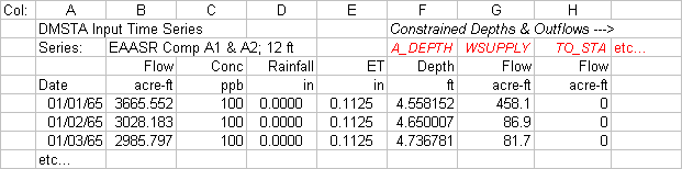
series to assist in reservoir simulations: Constrained time series would generally be derived from an independent hydrologic model (e.g., SFWMM) or from a user-defined operation rule. The time series are specified in the Project file in the following format:
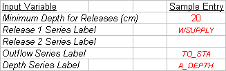
Depth, release, or outflow series are located in columns F and higher of the input series sheet. Up to 20 series (columns) can be specified, but only 4 can be used in any reservoir cell. Each series is assigned a label in the cell that is 3 rows above the first numerical entry. The flow & depth series (columns F & higher) can be in any order. Columns to the right of the first blank entry in the label row are ignored. Flows can be in any convenient units (cfs, acre-ft, hm3), as specified in table. Similarly, depths can be in ft, feet, inches, in, m, or cm. The Parameters sheet (Rows 23-28) contains input cells for assigning time series to a given cell:
The following constraints are applied in the simulation:
The predicted outflow series contains flows necessary to satisfy the water balance, in addition to any specified outflows. As consequences of these constraints, the simulated depths, outflows, and releases may differ from those specified in the input file. Differences may also be attributed to differences in the water budget algorithms between DMSTA2 and the independent model; (i.e., seepage computation, outlet hydraulics, dry-out algorithm, numerical integration scheme, etc.. ). If the time series label on the parameter sheet includes a leading asterisk (e.g., *A_DEPTH instead of A_DEPTH), the time series is not used as a constraint, but compared with DMSTA results. This provides a basis for comparing DMSTA and independent model results. This feature is relevant only for the Outflow and Depth series labels in Rows 26 & 27 of the parameters sheet. Diagnostic output for reservoir simulations is contained on the Reservoir sheet. The following information is provided for a user-selected reservoir (or STA) cell:
Typical reservoir simulation scenarios would include:
In one situation, the area, maximum depth, and pump capacity might be constrained. The outlet weir depth and minimum depth for water supply release would generally be low (but not zero to avoid concentration spikes) in order to utilize most of the reservoir storage capacity. The primary design variables would be the hydraulic discharge coefficients (a & b). The design game might be to adjust these values and look at the tradeoff between volume capture (bypass) and phosphorus removal, as measured by overall load reduction considering both the bypass load and the reservoir outflow load.. Some test simulations of reservoirs have indicated that phosphorus removal is relatively insensitive to outlet hydraulic parameters. Because hydraulic residence times are typically long, outflow concentration dynamics are relatively insensitive to short-term fluctuations in inflow and water level. While short-term concentration spikes may occur after re-wetting (depending on the weir level), average performance is governed primarily by surface area and secondarily by mean water depth. The dependence on area reflects the structure of the reservoir P cycling model, the steady-state version of which predicts that P removal depends only on hydraulic load ( Q / A). Sensitivity analysis should be performed in each design case. Scenario 2: Predict phosphorus removal for a design, water budget, & depths specified by an independent model
Examples of this type of application are contained in the PROJECT_RESERVOIRS.XLS input file distributed with the model. Marsh Applications The model tracks geometric mean concentrations measured in WCA-2A between 1978 and 2004 in four zones south of the S10 structures (0-4, 4-7, 7-10, and 10-13 km km), where phosphorus concentrations historically decreased from >100 ppb to < 8 ppb (near background). Inflow phosphorus loads decreased significantly after 2000-2001 due to upstream diversion (S6) and treatment (STA1W). Water depths and regulation schedule varied significantly during this period. One limitation is that the calibration may be affected by inflow & outflow seepage observed in this region; this aspect has not yet been explored. WCA-2A was also the primary basis for the steady-state STA design model (1995) and the Everglades Phosphorus Gradient Model (EPGM, 1996). DMSTA2 is designed to simulate long-term responses in a marsh subject to a given loading regime. While loads, flows, concentrations, and depths may vary significantly over time, drastic changes in long-term average loading regime may trigger cycling mechanisms that are not reflected in the model structure or calibrations (e.g. adsorption/desorption, soil P buildup and recycling, antecedent soil P releases, shifts in plant community). Just as the model is not designed to simulate the startup of an STA, it is not designed to simulate startup of a marsh just downstream of a new discharge, due to the above factors. While the simulations of WCA-2A following reductions in external load are reasonably successful, soil P cycling is likely to be more important in recovery mode. Initialization of the model storage term is a particular issue. Applying the same assumptions used in STA simulations and using the appropriate calibrations, the marsh simulation (using at least two iterations) would reflect a long-term dynamic steady-state if the inflow series does not contain a long-term trend. See above description of appropriate procedures to initialize the simulation if the input series contains long-term trends. DMSTA2 output includes both flow-weighted and geometric mean
concentration time series. The latter represents the geometric mean
concentration at the downstream end of a cell computed for days with the
water depth is greater than 10 cm (typically the minimum sampled
depth). Flow-weighted means are not measured in open marsh and less
relevant for assessing marsh impacts.
Model Updates and Enhancements DMSTA2 (April 2005) contains the following enhancements relative to DMSTA (April 2002). The enhancements were supported jointly by the U.S. Department of the Interior & U.S. Army Corps of Engineers. The previous version is no longer support or recommended for use. Enhancements to Case & Cell configurations:
P Cycling Model Enhancements:
Input Time Series:
While program output remains in metric units, input time series can be specified in a variety of units, specified in first row with 'Date' in Column A:
Output enhancements:
Operation Enhancements:
The following Version 1 features have been eliminated or drastically changed:
|
||||||||||||||||||||||||||||||||||||||||||||||||||||||||||||||||||||||||||||||||||||||||||||||||||||||||||||||||||||||||||||||||||||||||||||||||||||||||||||||||||||||||||||||||||||||||||||||||||||||||||||||||||||||||||||||||||||||||||||||||||||||||||||||||||||||
| http://www.wwwalker.net/dmsta/index.htm 01/17/2008 | ||||||||||||||||||||||||||||||||||||||||||||||||||||||||||||||||||||||||||||||||||||||||||||||||||||||||||||||||||||||||||||||||||||||||||||||||||||||||||||||||||||||||||||||||||||||||||||||||||||||||||||||||||||||||||||||||||||||||||||||||||||||||||||||||||||||